I believe they have a breakdown somewhere in their communication…
-e

I believe they have a breakdown somewhere in their communication…
-e
That sounds like a wonderful idea! But how do I send a PM?
Marty, I’ll just send you his email … the best Private Message. 
Could you please send me your delivery address?
So that i could check with shipping department what’s wrong with them. To find out which guy in charge of this.
Sorry for the inconvenience, thank you!
Thanks for the favor!
Some prototype would be realsed in middle May, and it need a adjustable Z axis bracket, this would make the laser module assembly heavy, so it’s only good for framework structure laser engraver.
So we have also design a new machine, similar as Laser Master 2, named as Ortur Laster Master - Model 400 (OLM-M400), this maichine should be released in Middle June.
I received my 20W Laser Master last week and had no significant issues getting it set up and working, thanks to the lessons for others here. But I do have several issues with focus and movement.
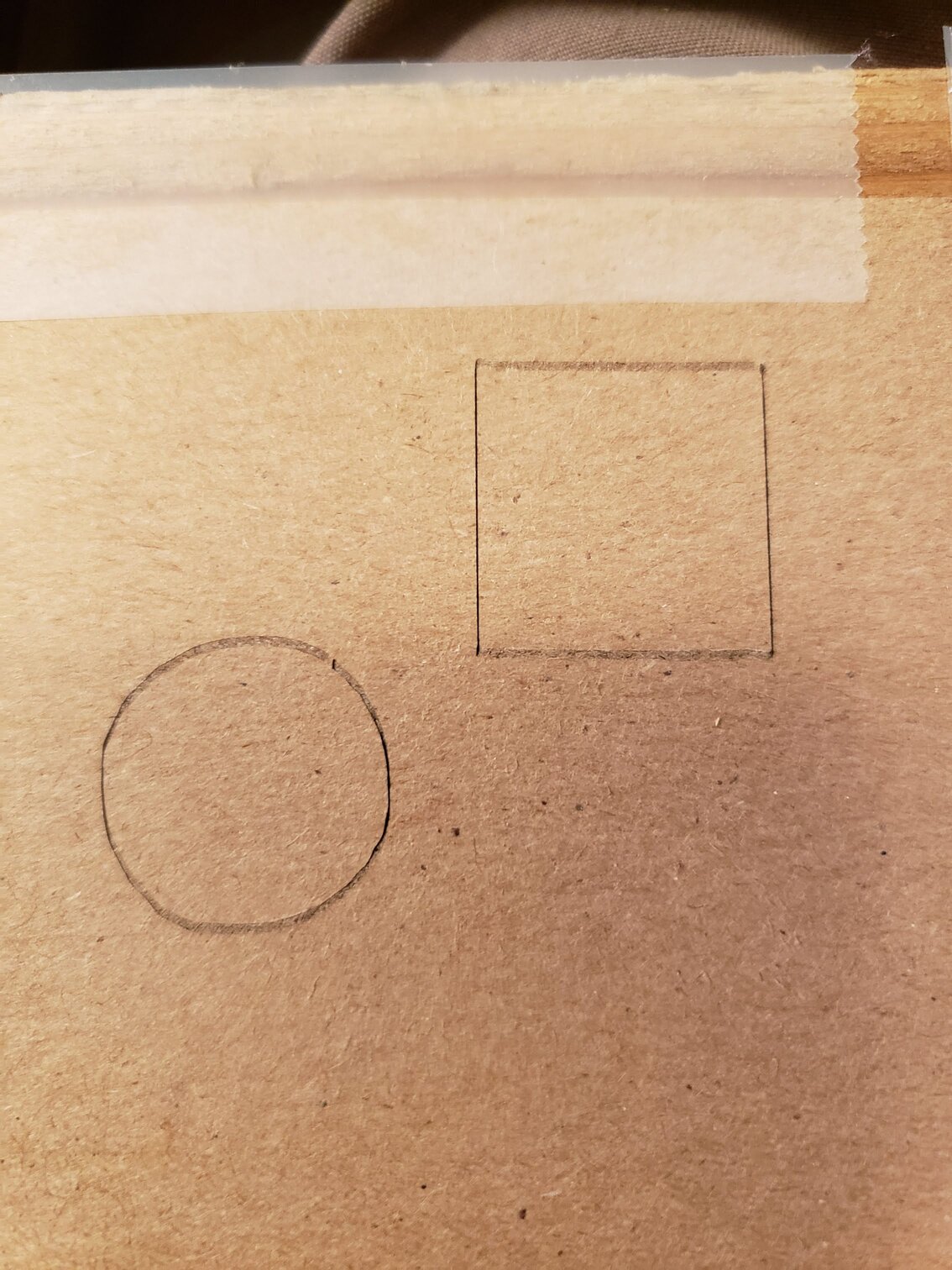
First, the laser won’t focus to a spot, it will focus to a sharp narrow line about a millimeter wide. Is this expected? You can really see the difference in etching X versus Y directions, per the attached picture. When etching a raster image, selecting the correct orientation will then have a great impact on the result.
Secondly, there does seem to be some wobble in the movement. In the attached picture, sides of the square seem to not be straight, and the circle isn’t very round. Should I adjust the tension in the belts?
Thanks!
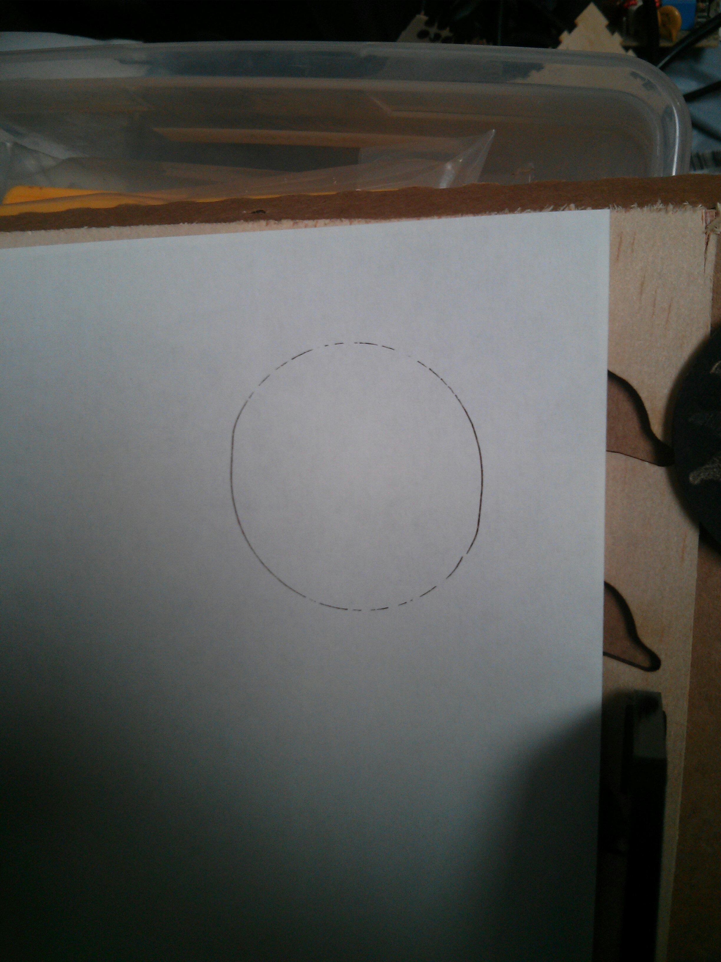
Very interesting. It made me try a circle and indeed it is NOT a circle. I tried a circle created in Inkscape and then I did a circle created in Lightburn and they are both circular on left/right(X) sides but on top(Y) and bottom there’s a flat spot.
Regarding the focus shape, I changed from the specified 55mm offset to a very close offset like 20mm, and then refocused. The bar was shorter this way, and it still etched fine. If I remembered my optics better, I would know what is wrong to cause the line. I suspect it either means there is a misalignment between the laser and the lens, not sure whether it is offset or angular. Or the optics aren’t great.
For the circle and line, I tensioned the x axis a bit, because it was easy to access. I also slowed way down, and things got a bit better.
For the purposes of etching simple items, it should be fine. I need to experiment a bit with images to get some good settings with the non-dot.
It was the Y axis belt on mine. I had just adjusted it yesterday but it slipped. Really had to tighten that screw pinching the belt. Gotta circle just fine now.
For the focus, I had to use a magnifying glass to help get the tight line. I also did a ramp test( see the thread on LED Laser Testing ) and got a focal length closer to the distance of a credit card instead of the sample plywood.
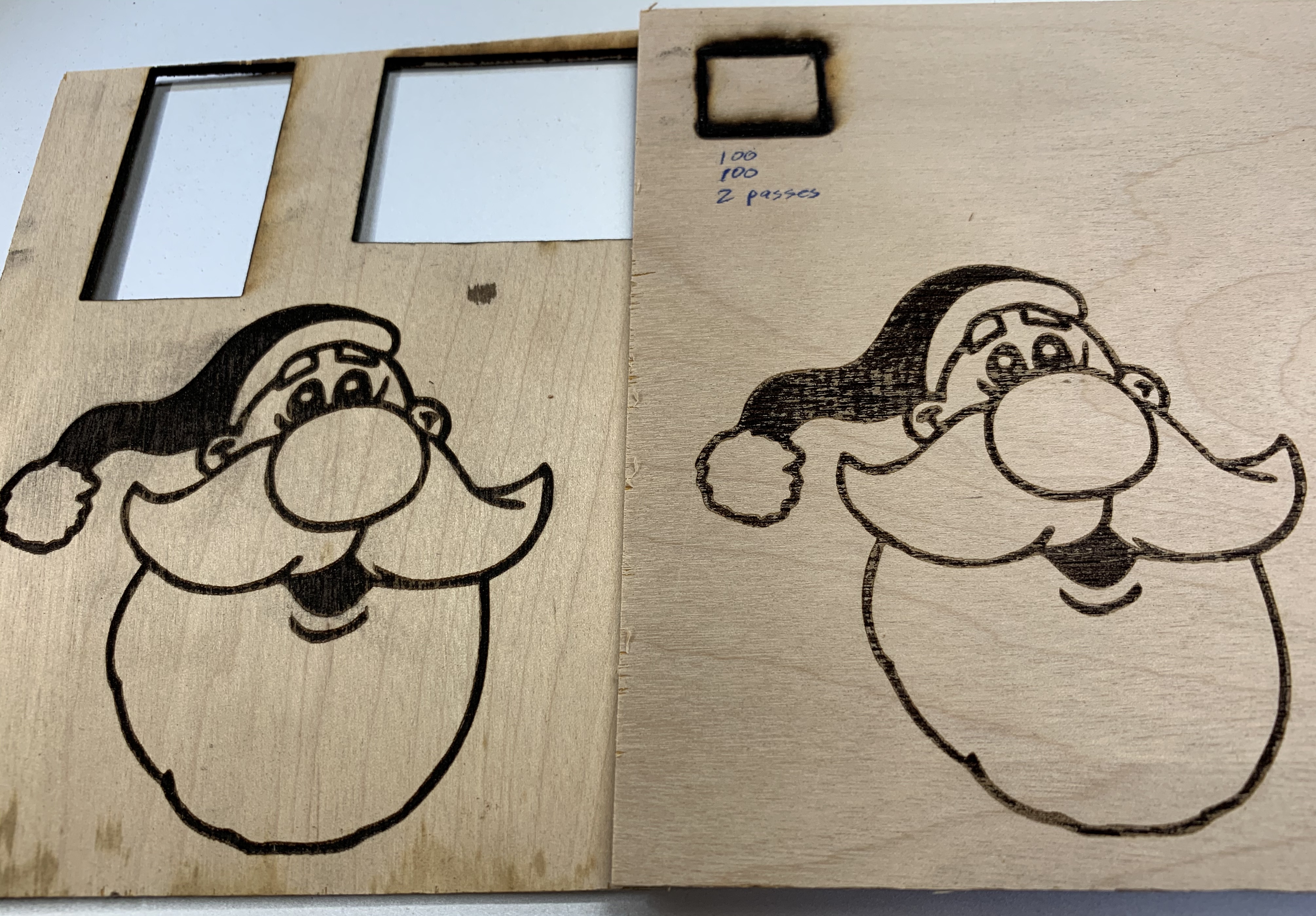
Ok, for anyone new here, I had bricked my motherboard and Doug generously rescued me. Things are working, but not like they were. See the pics…
Santa, cut when I first got my laser (left), and then, same file, same settings, same 2.4mm plywood. Note the 2nd one on the right is not nearly as clean and consistent as the one on the left. Even easier to spot the difference in person as opposed to the photo.
Second problem: Before bricking, piece on the left, I cut out 2 pieces, 100mm/min, 100% power 2 passes. In fact, the second cut is a window frame with 4 panes cut out of it all cut no problem. On the right, the square had all the same settings and all I got was a lot of burning and it went less than halfway through.
I’m not having a great deal of success with this thing…
Anyone else cutting and getting consistent results?
-e
If you have not touched the focus and have the exact same spacing I would try to compare your GRBL settings to someone who’d not updated their firmware. Use the $$ command. I think Travis might have posted his somewhere some time ago. I say this because maybe the acceleration and setting is different or something which would effect movement. Next I would try using the same piece of wood, not another section of the ply but that same piece on the left and try different areas which are still unused.
Good advice, but I’m wondering if it is worth the effort. If it is that touchy can you ever rely on it? I did check the focus and spacing before running the test.
I’ll check the GRBL settings when I get a chance…
-e
Focus is a big thing on any laser and this one is a bit tougher to get the focus set because the beam does not diverge very much. IIRC the CO2 beam is about 1/8" in diameter before it’s focused down to a fraction of a mm. Much easier to see when you’re above or below the focal point. Often even used for effects even.
And while I’ve not done lots of etching, I did do lots of testing of grayscale results once I replace my controller in the K40. Burning wood to get variations in color is highly dependent on the wood AND the lase power/speed settings. Much tougher than painting.
I’m only guessing at what could be different between your two sessions. And if it’s firmware settings I’d surely want to know what those first session settings were because that one came out quite nice. My Pog testing has been a painful play of a plethora of perimeters with a puny percentage of promise. I persist.
Fixing the X and Y axis tension on 15W Ortur laser
The holder for the Y axis belt was already as far as it could go. I could not pull the belt tighter, so I removed the screw holding the belt, pulled the belt out 1/4" and reassembled.
Here are some relatively new videos from Ortur about making adjustments to the 15W laser (posted April 19).
Very short videos on making adjustments to the 15W laser.
These are mixed in with videos about other machines made by Ortur 3D.
Ortur YouTube Channel.
https://www.youtube.com/channel/UC5g531FhcsljOSrK72Lwm8Q
Adjust X belt tension
https://www.youtube.com/watch?v=FZkdCSj9IG8
Adjust tension of Y belt
https://www.youtube.com/watch?v=1pZe7BA127o
How to adjust the eccentric nut to fit the X and . . .
https://www.youtube.com/watch?v=fpw8d9xEohU
Other topics include
If the X axis assembly is wobbling
If the X axis and Y axis is not at 90° angle
Etc.
FYI: This video shows that the green glasses really do stop the laser light.
See minute 5:15.
What Can You Cut With This “15W” LASER Machine?
https://www.youtube.com/watch?v=djRRxGXyACY
Thanks for the links Marty! I have a little warning - when you pull some belt through the tightening nut for the Y-axis, You can’t take up too much or the carriage will hit the tightening block before it reaches the home limit switch. If it doesn’t properly home, then it won’t operate correctly.
A question was raised about changing Lightburn’s default Text settings.
To see all the settings in your Lightburn app,
File --> Open prefs folder --> click on “pref.ini”
The file has many (all?) settings.
Avoid changing the file unless you know what you are doing!
[ On my Mac, filename = “pref.ini”, located in folder
Users/(Username)/Library/Preferences/Lightburn]
I copied the file to another filename with extension “.txt” and opened it with a text editor. A search for “Fonts” showed this:
“DefaultFontHeight”: 25,
“DefaultFontName”: “Arial”,
Presumably, these parameters could be altered in the pref file.
Didn’t see any other references to fonts (HSpace, VSpace, alignment, etc).
@Justin-Ortur , I have to ask, with all the issues cropping up about static electricity buildup, have you considered changing the wheels to ones with less friction and less slipping so less static buildup?
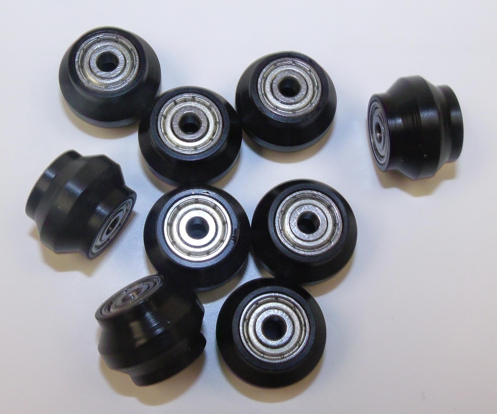
I built a Delta type 3D printer years ago using Misumi extrusions and a company made wheels which worked great. The design has a ridge in the center of the wheel just enough to ride in the slot with little friction as it’s just holding in laterally but the main difference from the wheels Ortur and Creality use is that these wheels have flat areas on the sides of that center ridge which is where all the forces are applied. Here is a picture showing wheels just like what I’m talking about.
These are smaller in diameter than the wheels currently used on the LM/LM2 but the concept remains the same.
Thanks for the advice and i have forwarded it to the engineer team already.
By the way, on about the tested solution of this issue, for your reference: https://ortur.tech/documentation/olm2/Ortur_Grounding.pdf