CNC Plugs for Cutting Board

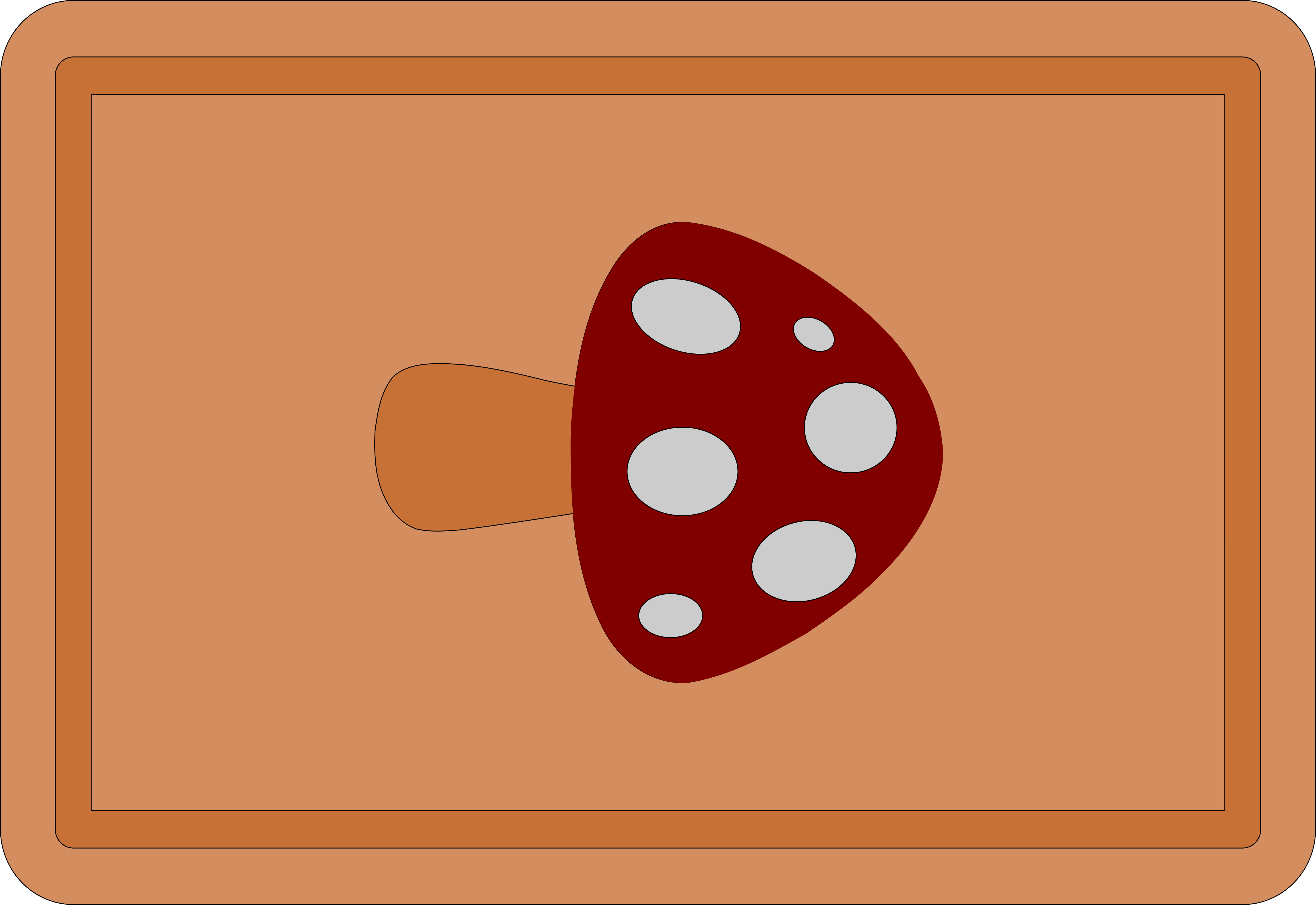
I’m working on a cutting board that I want to embed a shape in the middle that goes all the way thru the cutting board. Enclosed is a drawing of what I’m doing. Each color is a different type of wood.

My question is the size of the pieces that go into the other parts of the board. Currently I have the spots and the mantle cut out but the spots don’t seem to want to fit into the holes. I supposed with some sanding and a mallet I can make it work. But should I account for a small separation between the cuts? Or should the same outline be good for both the inside and outside pieces?

My answer is based on cutting mortise and tenon joints with a CNC. You should use the same vector for both cutting the inside piece and the outside piece. If your CNC is tightly configured and you make the final pass an onion skin cut (eg. 0.01”) then the fit will be perfect.

That said, you’ll likely want to leave a tiny gap for glue.

Thanks. That is what I was thinking. I’m using Carbide Create. In order to have the final pass very thin, would I need to create a new toolpath to do that?

Checked the current version of Carbide Create; a second offset vector would be required.
If you were using Vcarve then a final onion skin pass can be generated automatically.
It’s just a check box in the Profile Toolpath and specifying the thickness of it.

Below is the check box from Vcarve followed by a description of how it works.

If cap into the board gives you trouble, you could cut out and glue the spots before you cut the outside of the cap. That way any stresses from the fit or the gluing won’t distort the shape of the cap.

Travis is right on in his response. I’ve done lots of mortise / tenon joints and 10 - 12 thou (5 - 6 each side of joint) will give you a nice fit that you don’t have to use a mallet for.

If CC does not have a “final pass” function the Offset Vector function would do the job. I use this frequently when I want to make a mortise feature fit into a tenon.

In the future consider growing your skillset into doing more traditional inlays that don’t go all the way through the board. This would reduce any possibility of splitting if a “through” inlay’s wood type expanded / contracted at a different rate than the board. A quick Google search came up with the following.

Easy Inlays with Carbide Create – MIND BLOWN! - YouTube

Good luck!

Perry

2 Likes

For those wanting to do similar things with Fusion 360, what I’ve done is design line to line. It’s easy to create the multiple parts this way, either using edges from one feature or the boolean “Combine” feature with the cut option. Then use a negative “Stock to Leave” when setting up the toolpaths to get the desired clearance/glue gap.

1 Like