Fusion 360 SIG - Fruit Bowl and Shaper Origin

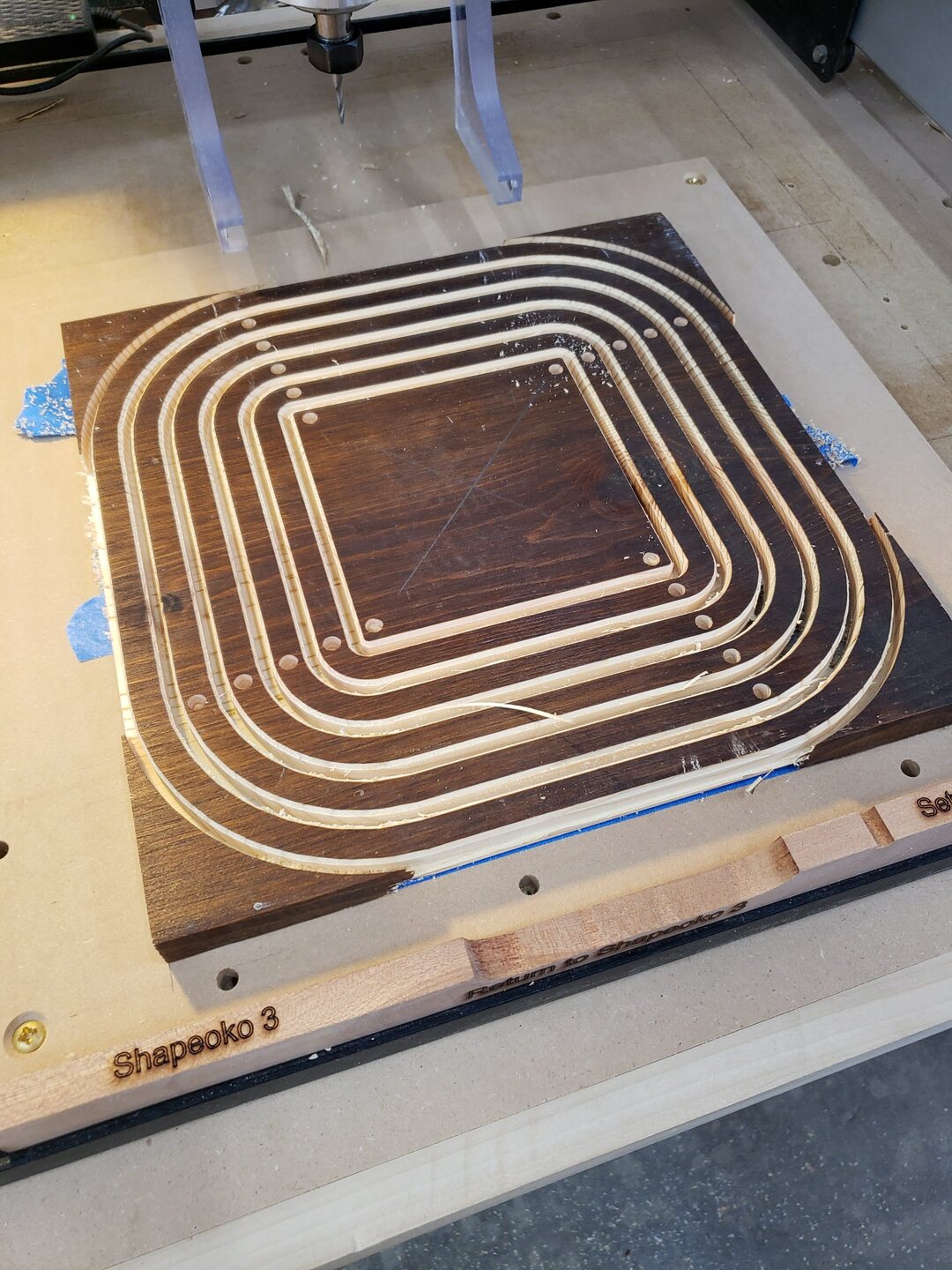
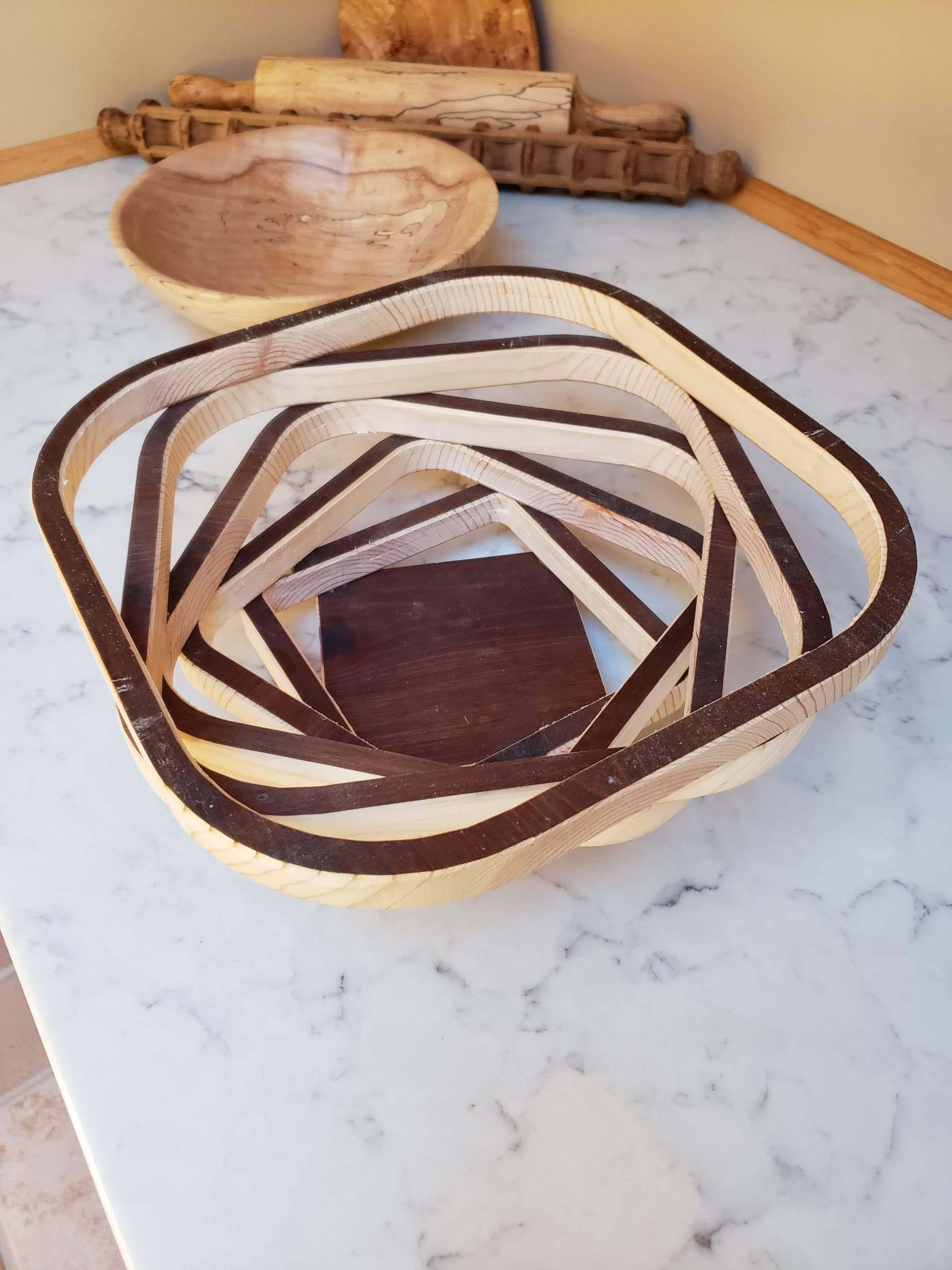
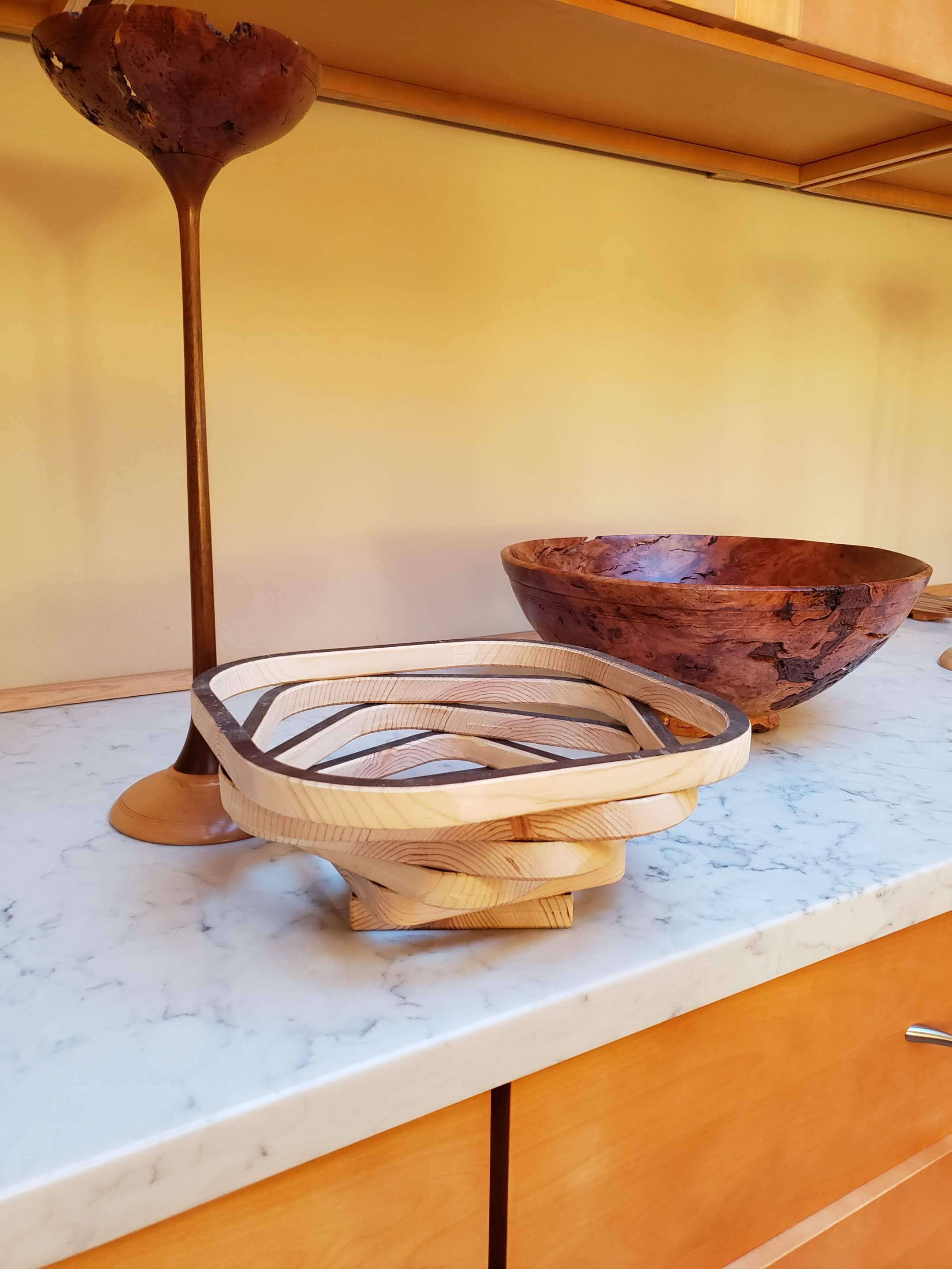
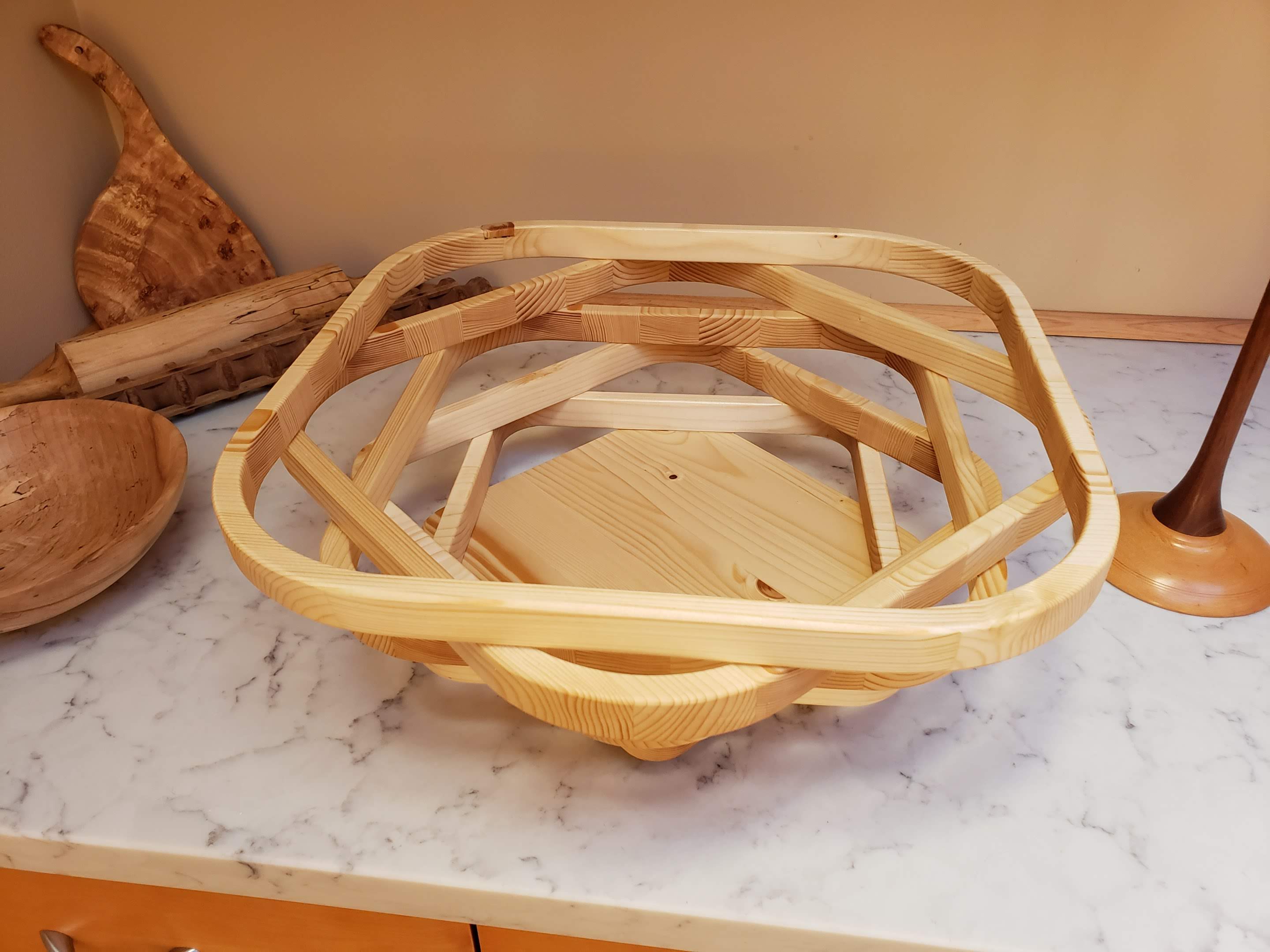
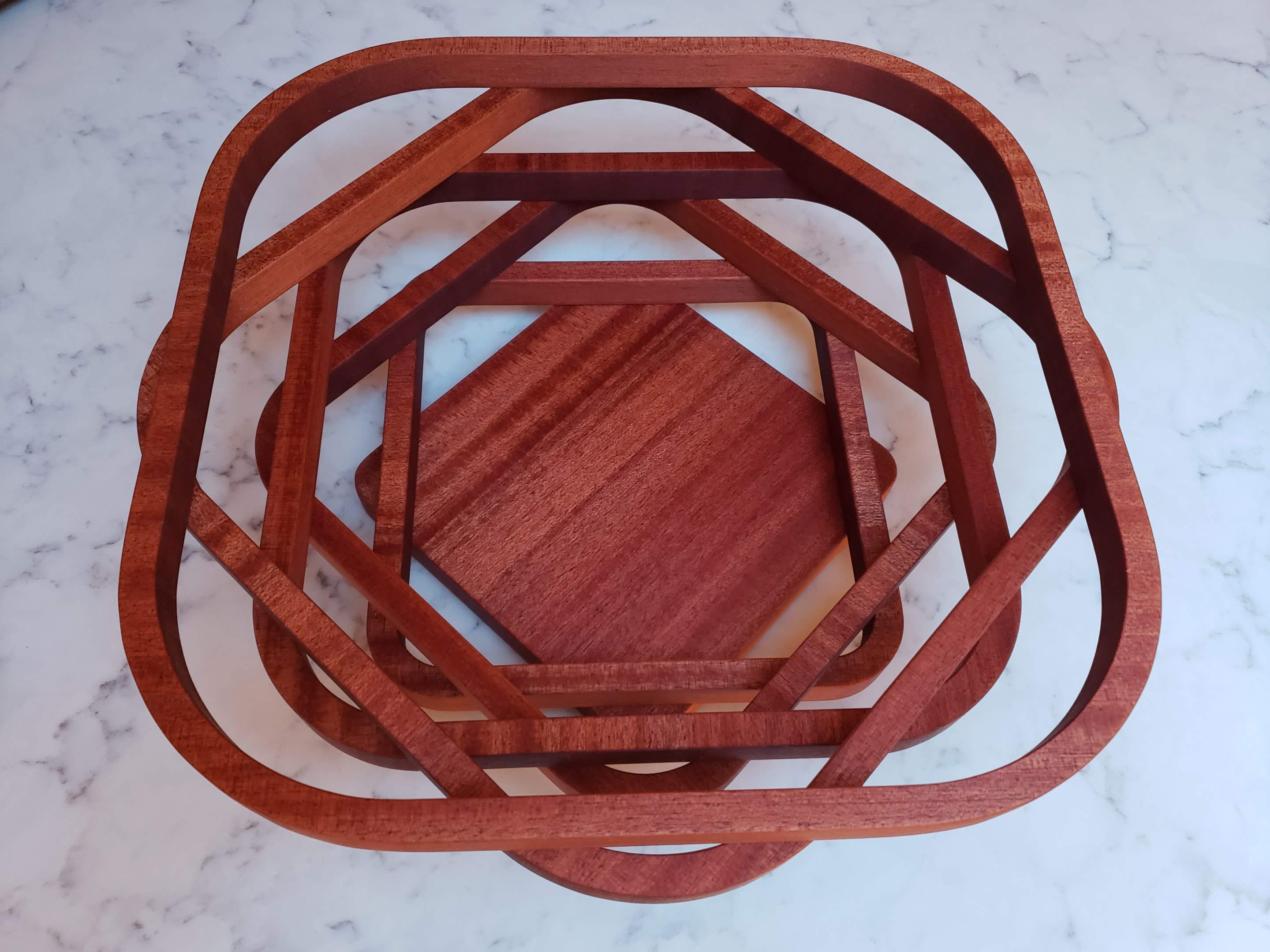
On Monday we looked at a parametric fruit bowl design intended to be created using a CNC router and single piece of wood. Well, a single piece of material, for grain orientation reasons it might be a lamination of multiple pieces of wood.

The highlight of the session for me was Travis introducing the Shaper Origin. I didn’t really understand what I was seeing about this product online until he explained it clearly in the session. It’s an amazing tool - I’m trying to figure out how I can justify the expenditure :slight_smile:

We had a question from the group about copying a component in an assembly. I suspect that the issue comes if we haven’t activated the correct level of the assembly. I will make a little screencast of the process and post it to the forum soon.

Here is the video of the session: https://youtu.be/4xpwmXEVCW0

Here are some timestamps of the video:
0:00 Ortur Laser discussion
9:45 Question on duplicating parts in an assembly
12:00 Fruit bowl project
13:50 Parameters used
24:12 Discussion of exporting cut file to Vcarve
28:20 Discussion of wood grain issues
34:45 Experimenting with different parameter values to hone the design
36:50 Great suggestion for animation of design
40:00 Discussion of cutting by CNC
45:00 Other CNC diversion
50:00 Travis presents Shaper Origin
1:19:45 Howard’s food branding and other diversions

Here is a link to the Fusion 360 file of the bowl: https://a360.co/3hJ2y1d

Here is a link to a Vcarve file of the bowl: https://www.dropbox.com/s/xe1ahchd99vcf4y/fruitbowl.crv?dl=0

A number of good suggestions came from the group regarding the fruit bowl design. The idea of using dowel pins to assemble the bowl, and making a “flattened” 3D file of design that could be imported directly into Vcarve for the CNC were particularly helpful. I am taking the next steps with this design, and will post the file and a screencast explaining it once I have it finished. It will be parametric, structured to expect to be CNC routed, complete with holes for dowel pins that are parametrically driven to adjust when other parameters are modified.

The bowl seemed so simple, and has gotten much more interesting thanks to the input of the whole group!

Back to the question of how to create a copy of a component in an assembly. There are several items that are important when you copy a component:

  1. Make sure that the correct assembly in which the component is located, is selected and activated. You should see the circle with the dot beside the name in the browser tree.
  2. Be sure that the component is defined as a component within the assembly, not merely a body within a part.
    Here is a little screencast I made about using this feature:
    https://screencast-o-matic.com/watch/cYQrYudfkU
1 Like

The fruit bowl design has been improved and updated. It is now a 2 sided design complete with holes for dowel pins per Doug’s suggestions. It is parametrically driven (with caution, take small steps at a time or F360 gets confused) so you can modify the parameters to fit your material dimensions and aesthetic preferences.

I’ve used the Autodesk screencast tool this time, which means it is hosted by them. Not sure if this was a good idea on my part or not - we’ll see if there are any repercussions.

Check it out if you are interested, and any questions or feedback are welcome!

https://autode.sk/32RqD1K

1 Like

I appreciate your help with this process. I did not realize it was so complex. The video helps a lot.

OK, I downloaded a 3D file of the flattened bowl from Fusion 360 to Vcarve and made a rough prototype of the fruit bowl out of a scrap piece of 1x12 (.75 x 11.25) that was stained. I left the stain on to make the pictures easier to see (not just because I was being lazy). Here are a few pictures of the machining and the assembled bowl.

On the Shapeoko:

I cut from both sides to get the dowel pin holes and chamfers on both sides. I also cut the slots from both sides because my 1/8" endmill is too short to reach the whole way. I was running short on time and did a rough registration using pencil marks on the spoil board and a spacer board in front. This left a tiny bit of offset in the cuts that I had to sand out, but I got lucky and it was better than expected.

I used a 22.5 degree twist angle to get more of a spiral look, which is evident when viewing the assembled bowl from above.

I like the spiral look, but from the side the effect is less obvious and 45 degrees might look better.

I learned a few things doing this that I would like to share:

  1. Despite the endgrain on 2 of the 4 sides of each ring, they feel strong enough. Any suggestions on what woods would be best for flexural strength in this configuration? I’m guessing this scrap is fir or spruce.
  2. The 1/8" endmill made the 1/4" dowel pin holes okay, but with a bit of vibration and possibly some bit flex, the holes were too narrow and I had to drill them out at 17/64" to fit the dowels. I would suggest oversizing the “dowel pin diameter” parameter a bit to ease assembly.
  3. For a quality result instead of a rough prototype, I would suggest creating a spoil board with tooling pins or dowel holes so that the 2 sides can be more accurately aligned when flipping the board.
  4. When buying a 1/8" endmill, it might be possible to get a longer one and make the slots and outline from one side to avoid the little bit of offset from cutting from both top and bottom.
  5. Fusion 360 failed when exporting an STL file, not sure why. I used an OBJ file instead, and it seems to have lost the chamfers. So I just created them in V-carve using shallow profile cuts directly on the lines on each side of the slots. In my case, I then decided to use a 60 degree V-bit because that’s what I had in my hand.
  6. I used 1/8 inch slots in the design, and a 1/8 inch endmill, telling V-carve to use pockets for the slots. As a result, it cut both sides of each slot, meaning the bit was spinning in air half the time. No big deal if you aren’t running short on remaining shop time. I could have used a profile cut on the “outside/right” of the inside edge of the slot from the 3D file.

After seeing the prototype, I’m not sure if 22.5 degree twist looks better than 45 degrees after all. I would like to make and finish a nice bowl , but a bit larger. Perhaps start with more like 14 inches and thicker like 1 inch or so. And I need a more experienced woodworker to suggest the material.

If you want to make one, be very careful about Fusion 360 messing up the holes when you change parameters. Once you select the parameters you prefer, I’d be more than happy to alter the design for you and send you both design and 3D export file for your own use.

1 Like

Chapter 2 in the Fusion 360 plus CNC Fruit Bowl project.

I picked up a laminated pine board at Lowes, it was 18x24x1. I thought, “why not make a large bowl, almost 18” wide? So I modified the Fusion 360 design to use this larger size, plus I decided to go with a 45 degree twist to make the bowl look more “regular” and perhaps be a bit stronger. Here is the result:

The result wasn’t perfect, I learned a few additional things I will share:

  1. 18" is really big for a bowl.
  2. I only used 2 dowel pins per tier to try to keep it stronger. But that made it a bit more difficult to tell where to apply glue etc. I would advise 4. I since purchased some 1/8" dowel so that I can use smaller holes in the wood. 8 dowel pins might even be better, though it would likely be a challenge to line them all up for assembly.
  3. I again used a v-bit to make chamfers on the edges of the tiers. I think this was a mistake. It makes top-to-bottom registration too critical. Better to skip the v-bit chamfers and just round the sharp edges manually, I use sandpaper. If one has skills with a spokeshave or scraper, that might be a better way.
  4. I used 2 holes at 3/8" as tooling holes to align top to bottom using 3/8" dowel pins. I put holes in the bottom side (which I cut on the CNC first) and in the spoil board. This alignment wasn’t great - need to use deeper holes and longer pins, and 4 of them.
  5. The alignment problem was particularly painful because although I bought a long 1/8" endmill, I was a bit nervous to use it so I used the shorter bit and cut from both sides. I had a misalignment on some sides of up to 0.05".

So progress, but still a learning experience. This gave me the confidence to try to make a really good bowl, or strike out spectacularly. I cut a third bowl on Monday. Today I am cleaning it up and hope to finish it. I’ll post particulars when I finish.

1 Like

Chapter 3 of the Fruit Bowl story…

This was the time I was supposed to get everything right. I started with a beautiful 14 “piece of sapele. I had 1/8” dowel on order, so I used 4 holes at 0.130" per tier. Things mostly worked out well, though when the dowel arrived it was basically 0.110" or less. This resulted in more slop in the pins than desired, but it still provided enough guidance to assemble the bowl.

The sapele machined very nicely. I used 4 tooling holes between the sapele and the spoil board to make sure that the dowel pin holes were accurately located on both sides. I skipped the chamfers, and used my long 1/8" endmill to make the full cuts. The result looked much better for not having the chamfers - I just broke the sharp edges with sandpaper. I finished the wood with cutting board (mineral) oil, which darkened the sapele considerably.

On the Fusion 360 side, I had hoped that removing the chamfers might make locations of the dowel pin holes more stable, but no such luck. The model still loses some sketch planes when making significant changes to the values of some parameters. This is clearly a Fusion 360 weakness.

The bowl will become part of the digital tools display at the member shop. If you are interested in making one, please let me know. If you provide details of the size of material you wish to use, I’ll adjust the design file accordingly. I exported this as a Sketchup file and imported it to V-Carve as vectors. The holes come out well, and I used the outside edge of each tier to drive a profile cut. I didn’t catch it, but the outside most profile was a bit segmented, so I needed to sand off the radius a bit more.

I tried other approaches from a file export/import point of view. The STL or OBJ files segmented each radius. The holes sometimes show up as blurry bitmaps rather than round vectors. Since this is really a 2.5D project, working from vectors went well.

1 Like