LinuxCNC testing on 3D printer shows it should handle laser engraving

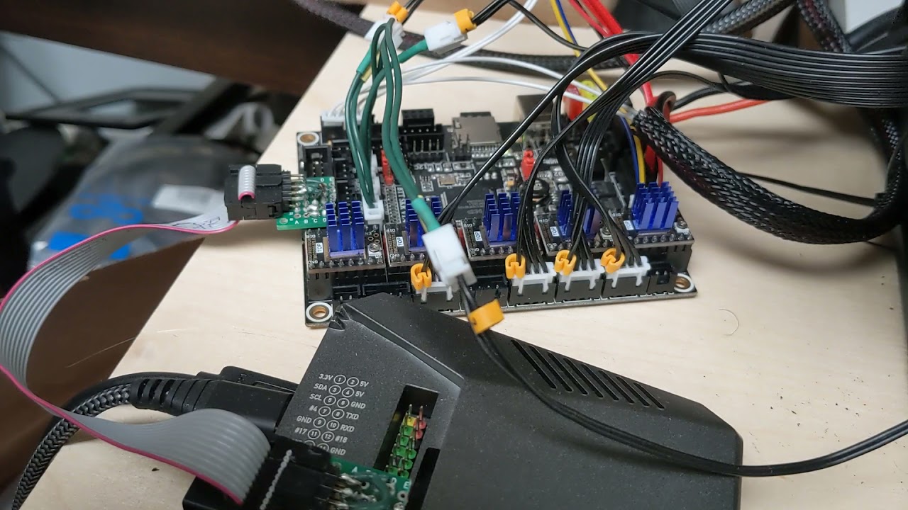
I have LinuxCNC on a Raspberry Pi controlling a $45 3D printer controller board( SKR v1.4 turbo ) and as I learn more about LinuxCNC I find things to test features and capabilities. For example, the Trajectory Planner handles lots of things dealing with acceleration, deceleration, etc and it does so by looking at the next command/move and many others coming up. These videos show what happens when the TP look-ahead is disabled and a good way to show it is with circles having many straight lines. The Arc Blend feature of the TP optimizes motion when it can. I created the file using LightBurn by creating a circle, setting the speed to 200mm/s and then set the feature type to Offset Fill with a 1mm offset per line/circle. The speed with the 50 segment look-ahead buffer shows that this LinuxCNC setup should also work fine on the K40 laser cutter.

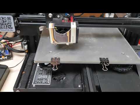
Here are 2 videos showing LInuxCNC arc blend buffer testing.
One with a 1 segment arc blend buffer size(arc blend disabled):

and a video showing LInuxCNC with a 50 segment arc blend buffer(arc blend enabled):

Both at 200 mm/s? The Arc Blend enabled was ridiculously faster in that comparison. Why does Trajectory Planning have such a dramatic effect? It’s not obvious why a large look-ahead buffer would allow it to speed up so much.

BTW, do you know if there’s a F360 post processor that works with Linux CNC?

Yes, the LightBurn generated gcode did not change and the only thing I changed on the LinuxCNC side was a config setting, ARC_BLEND_ENABLE=0/1 ( disable/enable ). By default, without setting that config variable Arc Blend is enabled and I also tested and verified that was true.

The large difference in speed is because when the Trajectory Planner only looks ahead 1 line segment at a time, it literally has to complete the line segment move including accelerating and decelerating before the next segment is processed. With a default of 50 segment buffer(look-ahead) the TP can see smooth transitions from segment to segment and therefore does not decelerate between segments.

LinuxCNC has a tool called HalScope which is a software Oscilloscope for showing graphical plots of functional parts of the system. If I were to pick the X and Y axis/joint and their acceleration plot it would probably look a jaggy with no look-ahead and probably a straight line with the 50 segment look-ahead buffer.

What’s cool about LinuxCNC, and other ‘real’ CNC control systems is these things are controllable and settable in the configuration and not programmed into the firmware. The people I’ve talked with who do CNC machining not only know their speeds/feeds bits/endmills but they also have in-depth understanding of gcode and what things effect machine performance with different materials. Blows me away how geeky these people are.

And I’m finding lots of interest from them regarding 3D printing. No doubt when I show LinuxCNC running on the K40 and mention laser diode modules for CNC machines they will be jumping on that too.

BTW, LightBurn didn’t generate a spiral while doing the Offset Fill operation and instead does circles and changes the radius so many circles inside of circles. In the video you can see the motion stop and then start again on each revolution. If I find a tool to create a spiral, or create a spiral vector in Inkscape, the result should be even more impressive as there will not be any deceleration and acceleration on each revolution.

As for Fusion 360 CAM post processor goes, I certainly would hope so considering LinuxCNC( also called EMC or EMC2 ) has been used on CNC milling machines for decades and it is the default controller for Tormach and I think others.

LightBurn, Prusa Slicer and Slic3r support LinuxCNC gcode formats. It’s really one of the few which support most all of the GCode standard.

ha, F9 in Inkscape creates a spiral so I counted the circles LightBurn made at 1mm separation(42 of them ) and set the loop count of the spiral to 42 then resized it to 83mm as is the LightBurn circle and voila, the same test but now with a spiral. ie I imported the inkscape sprival SVG file into the LightBurn project, turned off the original circle layer and set the spiral layer speed to 200mm/s and generated the gcode.

very smooth and very fast.

1 Like

For each of us geeks, a theme. :joy:

1 Like

I have the K40 running LinuxCNC and Remora but ran into a problem driving the laser power in gcode. Spindle control Gcodes are what’s used to drive lasers with a range of 0-1000 on the “S” command.
10% power : M3 S100 or just S100 if the M3 command was already issued to turn on the spindle ouput.

But for CNC machines(the big ones) the spindles are driving with a 0-10V signal into VFD spindle controllers so the PWM used in Remora is a Pulse Density Modulation type so freq changes with pulse width setting. That really screws up our lasers which want a fixed frequency and only the pulse widths varying.

So I’m working with the developer of Remora to enable another pin definition for this “normal” type of PWM. GRBL, Smoothieware and others provide a configuration parameter for the clock frequency and generally you have to live with the results at that frequency. BUT, out lasers work optimally for engraving at a different frequency than they would for cutting so having a way to dynamically vary the laser control PWM frequency would be a handy thing. That will be supported in Remora!

I will probably remap the M3 command so that it support another parameter( F or P) such that
M3 S100 F400 will provide a 10% pulse at a clock frequency of 2.5KHz(400uS period)
M3 S500 F20 will provide a 50% pulse at a clock frequency of 50KHz( 20uS period)

For some incredible research on this:

I just heard from the Remora developer and both fixed frequency and adjustable freq/period hardware PWM is now in the main code branch!

The firmware config.txt pin definition now looks like this:
NOTE: remora.SP.0 is defined for the PWM pulse widths and remora.SP.1 is for setting the freq/period.

{
“Thread”: “Servo”,
“Type”: “PWM”,
“Comment”: “Bed heater PWM”,
“Hardware PWM”: “True”,
“Variable Freq”: “True”,
“Period us”: 200,
“SP[i]”: 0,
“Period SP[i]”: 1,
“PWM Pin”: “2.5”
},

I should have my K40 operational with this and can do some freq tests for cutting and engraving.

Doug, that’s cool to have Linux CNC capable of driving CO2 lasers but what’s the draw of using Linux CNC for this? Is it just having the one CAM software to rule all digital tools? A laudable goal I suppose but I’m very happy with LightBurn for lasers, aren’t you?

LinuxCNC is not CAM software, it is the motion controller and gcode parser part of the picture. And I still use Lightburn but don’t use LightBurn for the GCode sending part. LightBurn is the CAM just as on the 3D printer Prusa Slicer is the CAM for 3D printing. Both LightBurn and Prusa Slicer have builtin GCode senders which stream the GCode they generated to the firmware on the machine which parses the GCode and figures out how to interpret that to move motors and turns things on/off. LinuxCNC does this stuff in realtime with realtime user control. ie when you say stop it stops instead of stopping after the commands in the buffer finish. Tough to explain it all but will try an overview.

LinuxCNC has always been a complete motion control system for machines of all types it just used to cost so darn much and take up so much space to use a real motion control system for DIY projects like RepRap and home CNC. So RepRap had to comprimise with a low cost low capability control hardware and firmware(reprap, marlin, sailfish, etc ). They all were created because it was too expensive for the hardware to run a full motion controller software. They are all slowling growing up to run on 32bit processors and each are adding more GCode support( G2,G3 for example ). But now the opposite is true, ie the hardware with the performance needed to run the high-end motion controller software has become so inexpensive that that for under $100 it’s doable.
And I’m leveraging the fact that these 32bit ARM controllers for 3D printing( SKR v1.4 / MSK Sbase v1.3 / Smoothie / Cohesion / etc ) are so popular they are inexpensive and capable of doing the realtime stepper motor, encoder, etc control required for the motion controller.

Also, the use of stepper motors has limited capabilities because of edge cases when steps are missed by the motors due to periodic load peeks. LinuxCNC was designed for use with encoders and now inexpensive encoders like the AS5047 are under $20 and can be mounted to the back of a stepper motor. Had Carbide3D been using a cheap encoder on their belted Z axis you guys would never have known there was any position slipping. But they had to throw a hardware solution at it for hundreds of dollars.

Don’t get me wrong, LinuxCNC is not for everyone just as Linux was not for everyone until someone starting making it pretty and easier to use. People have no ideas they are using Linux when they use a Tivo, or an Android phone, etc because someone made the UI easier for them to use.

Tormach is one CNC vendor who uses LinuxCNC and created their own UI. And LinuxCNC is designed with capabilities to do almost click/drag UI building and there are lots of UI options already available to use with it. And if you look around, there are lots of 32bit controllers and firmware being used on 3D printers, lasers and CNC/routers so wouldn’t it be cool if there really was ’ One ring to rule them all, one ring to find them , One ring to bring them all, and in the darkness bind them’?

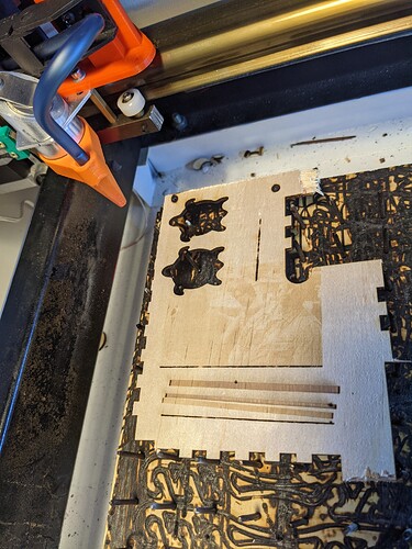
It’s WORKING! I was having problems with LinuxCNC parsing so many small moves( at 254DPI each move is 0.1mm ) and did lots of tests at 25% power, 15% and 5%. When there was parsing problems even 5% power was burning deep black lines instead of surface etching.

It may not look like much but it’s at 5KHz PWM, 5% power setting, 200mm/s dithering of a 75mm x 50mm image but it works. I can see Walter and Donny, can you?

Here is the original image:
lebowskibowling

I thought I was being fancy by using both the synchronous M67 command to control the laser power and the asynchronous M68 command. Turns out, putting the M67 command on the same line as the movement was the magic which resulted in the motion speed needed to allow there to be variation in power levels which can present variations in image perception. ie it scans so fast that 5% power is almost unnoticeable. But I can see it, can you?

I’ll do some tests changing the PWM frequency since I’ve seen in a number of places that different PWM frequencies provide different optimized effects for each engraving and cutting. I’m hoping to setup the system so that just a custom M code can change the PWM frequency for cutting operations and engraving operations and hopefully within one design/toolpath file. Then I will see how this handles grayscale.

1 Like

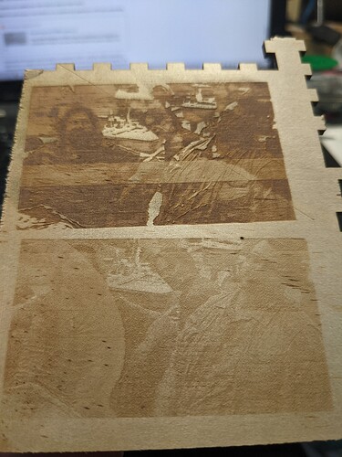
dithering and grayscale work along with changing the PWM frequency on the fly. Top is grayscale at 10% power and bottom is dither at 5% power. The white banding near the lower end of the grayscale image is when I changed the PWM frequency from 5KHz to 2.5KHz and then back to 5KHz. Cutting is supposed to be improved with 20KHz PWM frequency. You can see that at the higher frequency there is more depth to the engraving.

Realize that I did nothing to this image but let LightBurn convert to grayscale and I was not looking to get a good quality engraving. Just testing to see that I can get variations in engraving and at a good speed/performance. With this working, it’s just tuning to get the proper effect and results and that includes photo editing of contrast, brightness, etc.

1 Like

Thank you for sharing all of this! Amazing work.

1 Like