Wondering what steps to design this

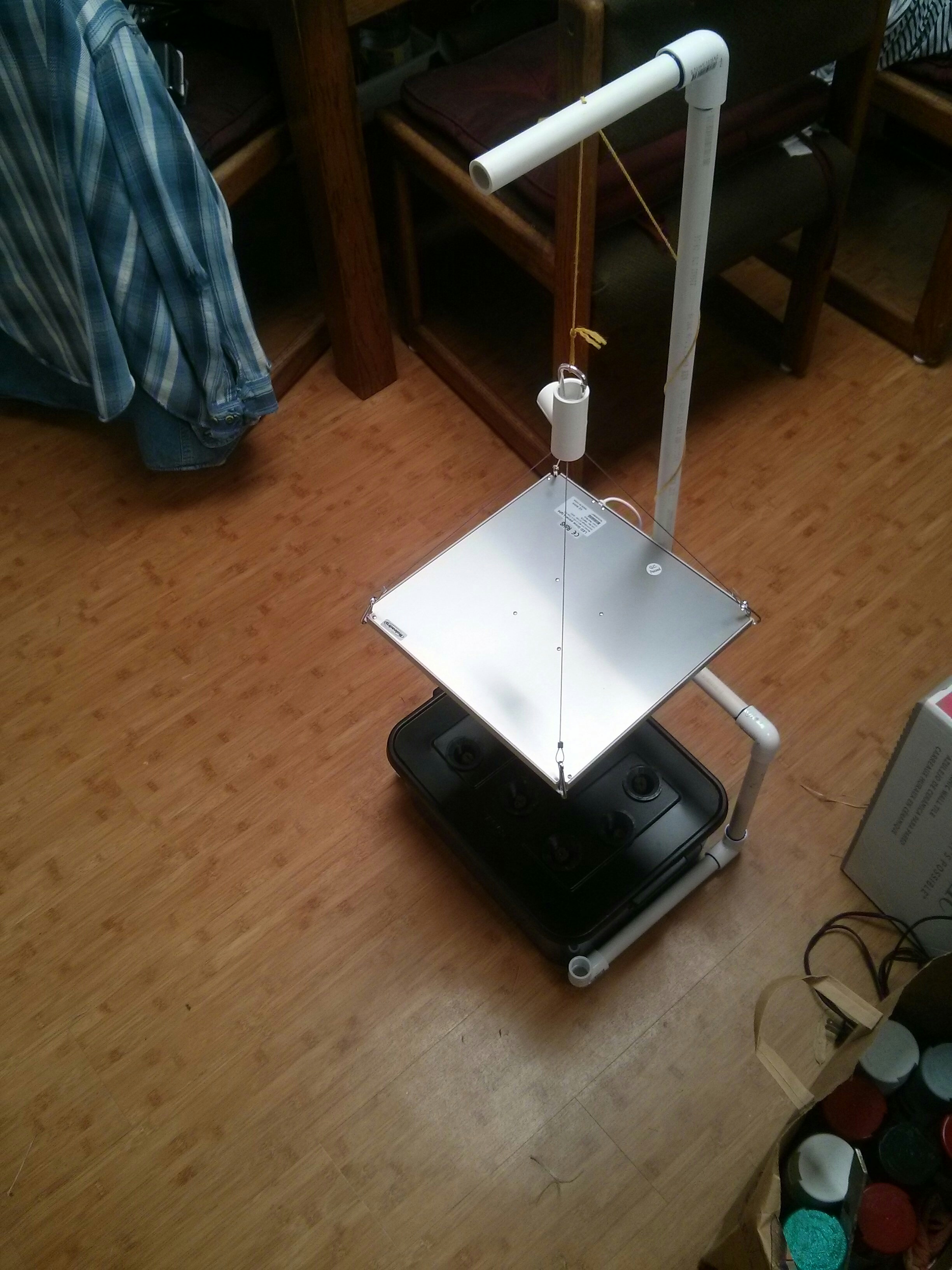
I’m designing a tabletop DIY Hydroponics system and working on a combination water level sensor float AND water circulation pump.

The water level sensor is just a magnet on top of a float which will lower from the top of the lid when the water reaches 2" below the lid. A reed switch outside the lid triggers the controller of low water.
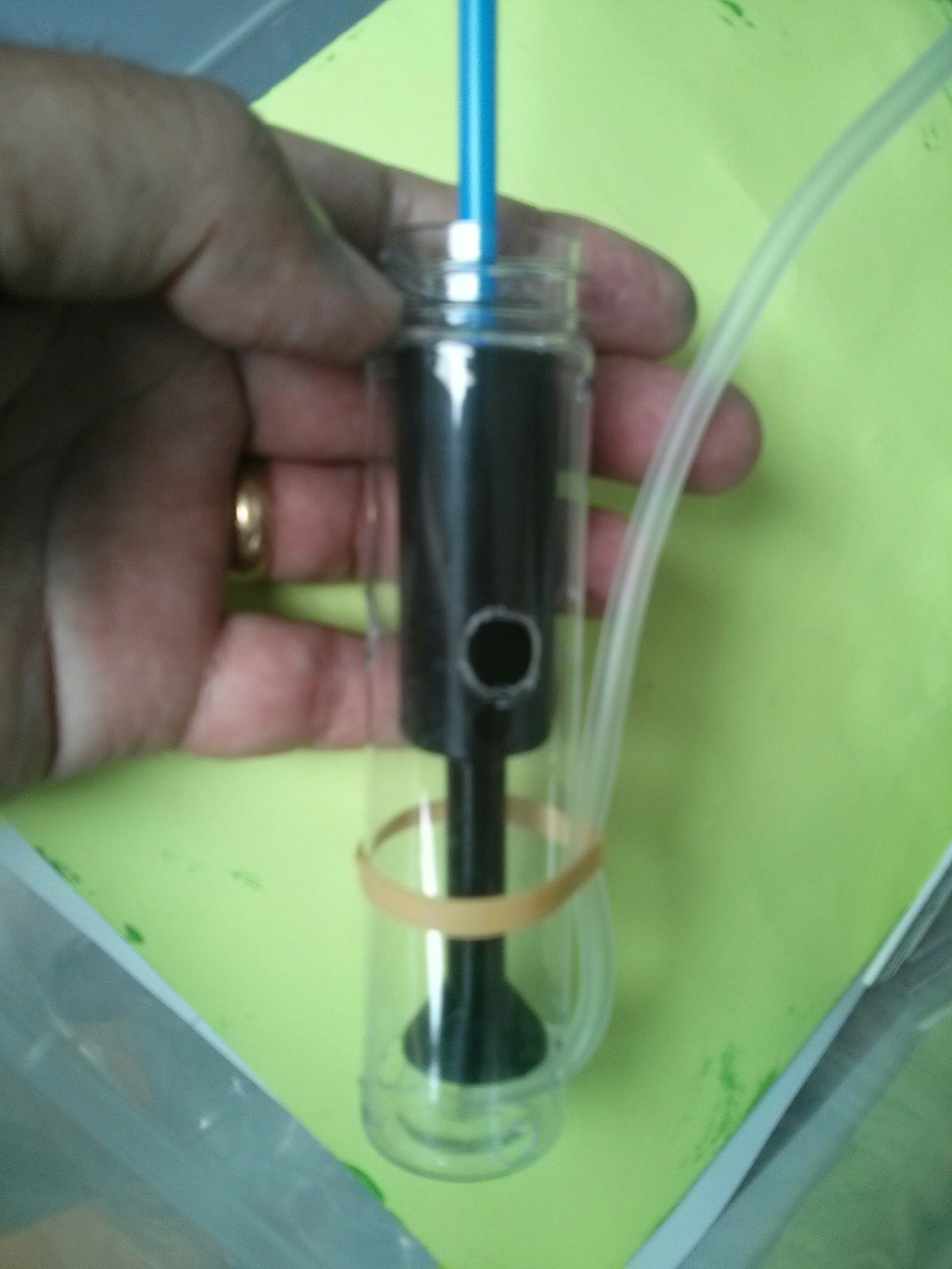
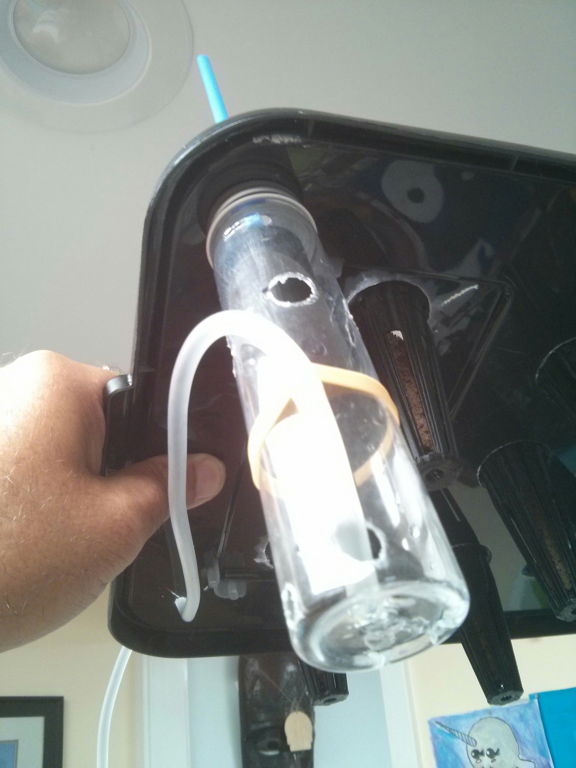
The water pump is a simple fishtank air pump through a channel. A funnel at the bottom lets air and water enter the pump channel and 4 outlets let water and air out.

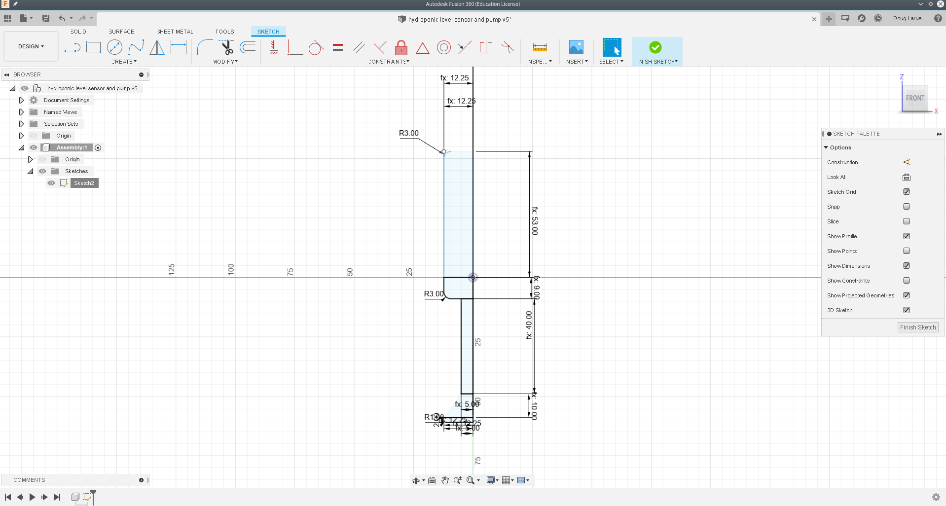
I’m about to bring this into F360 and I’m thinking about the construction process.
I can see doing a profile sketch and rotate it but the 4 water/air exit channels at the top of the pump section has me caught.
I also expect to be adjusting the air chamber ‘donut’ below the exit channels to fine tune when the float drops. The weight of the PLA plastic and infill percentage will effect buoyancy so I expect some experimentation.

Should I create 3 sections(bottom pump sketch, middle disc, upper float sketch) and combine those after using horizontal cylinders to difference/remove from center disc or is there a more elegant way to make a single sketch and remove the center channels afterwards?

Hi Doug, what shape are the exit channels? Can you add extruded cuts to the top of your pump section, and other extrusions as needed? I’m not sure that I fully understand your sketch.

You should be able to calculate the weight and volume of the float, assuming we know the density of PLA and the infill percentage is accurate. Using Archimedes, we should be able to calculate how high the float will ride.

In general, I prefer using multiple simple sketches and features rather than very complex ones. If you are making relatively thin walls (several mm for example) you have 3 options. The optimal solution depends a bit on the target geometry:

  1. Making solid features and then using Shell works well if the wall thickness is equal everywhere.
  2. Making surface features and then adding thickness gives you more flexibility.
  3. Using offsets to create more complex sketches is more hassle, but provides more design flexibility.

I’d be interested in how the tabletop hydroponics works out. A few years ago I tried a Deep Water Culture approach. It worked great for basil, parsley, lettuce, and the like. With tomatoes I got fantastic plants and lots of leaves, but not much fruit. I think I had the nutrient mix wrong - too much N etc. I still use a little Aero Garden to sprout my seeds but plant the tomatoes outside in the garden, and in pots. I also found that I needed to use some silicon in the nutrient to build stronger stalks, or things fell over and the lettuce was too soft.

It’s really just a long round cylinder with an upside down funnel like thing on the bottom. The upside down funnel is really a water pump which uses air bubbles in the narrow tube section to move the water.
But there needs to be holes in the side of the cylinder for the water and bubbles to escape. The exit channels/ports.

My drawing might be confusing in that I show the upper section hollow when in fact it’ll be designed as solid and using 3D printer Slicing settings I will vary the amount of air and plastic(infill).

I’ve sketched the profile as 5 elements so that I can manipulate parameters as needed. I figured I would revolve the sketch/profile 360 to make a round solid and then I would shell the lower funnel part before working on making the water exit channels/ports. BUT, for the life of me I can not see the sketch profile once I click the Revolve button. Sketch picture below:

I’m basing the hydroponics loosely around the AeroGarden Bounty size. My bucket is 15"L x 11"W x 6H and I 3D printed the cups. I’m using a Raspberry Pi running Node Red(NodeJS) to control 2 wireless/IP switches(Sonoff Basic) to control an LED grow light and the aquarium air pump.

This design I’m working on is a combination water circulation pump(uses air pump) and water level sensor/indicator. I will have a magnet on the top which will close a reed switch so that when the water is high/full the float pushes the magnet against the underside of the top cover. When water goes below the Low Water Line the float will drop from the top and the magnet can’t hold the reed switch closed.

This whole float/water pump thing fits inside a $1 plastic foodgrade test tube which I will just drill a few holes in for water inlet/outlets and air escape at the very top. Seems elegant if I can get it to work and I wanted few holes in the top cover and for everything to be attached to the top cover so only water is in the bottom bucket when the top is removed.

1 Like

@tim.peachey I was able to extrude in the sketch then select the extruded face(should have been a profile I could select) and then revolved selecting NewBody option. Crazy.

When designed, I want to build one too!

1 Like

getting there… V1 of the grow light hanger but v2 already designed and ready to prototype. V2 will have 2 vertical overhangs with 4 individual lines/holes so the grow light can be pulled right upto the overhang. Less flexing of 1/2" PVC and I can reduce the total height about 10" to the 24" intended.

It was a bit of a pain but I finally got something and it’s working perfectly.
To be capable of adjusting things for testing I had made the profile sketch out of 5 different segments and used constraints to link them all together. Seemed ok but I could not use Revolve after I closed the sketch.

What I could do was extrude the sketch and then revolve a face of that extrusion. I then hid the extrusion.

This led to issues with using the shell function but I didn’t know it. Tim found that out and let me know. But to get through the issues I had to extrude the design in 3 parts, shell those, then join them and then use the bevel function to create smooth transitions between joined parts.

OMG, all the problems I was having with Fusion 360 not presenting the 2D profile of the sketch in the 3D design space AND the problem I was having with the Shell command now working as expected… It had to do with the fact that I applied a couple of fillets to the sketch design.

Once I removed all the fillets from the Sketch, the 2D profile was usable in the 3D design space, Revolve worked as expected and so did Shell.

I wonder if other CAD tools work this way or if it’s just an Autocad-ism. Still learning things but this simple little float/pump combo design took 10 times longer to design than it does to 3D print. I can whip it out in 1/10 the time it takes to 3D print now.

Is the UV lighting under the silver square and can be raised or lowered as needed?

Watch out for those fillets! :slight_smile:

that is the Grow Light but no UV though…
https://www.amazon.com/gp/product/B01IVQ96KY

Doug, I can’t get the idea of a beautiful wooden housing out of my mind. Once you’ve figured this out we should talk about a group build. There’s the technology and then there’s the housing. It seems to me that the latter could be a joyful expression of personal creation by people in the SDFWA community.

Wouldn’t it be amazing to have a dozen different-yet-beautiful variations?

Keep us posted on your progress. Thanks!