
Rotary attachment for the Ortur
2 Likes
Normally $65.00 now on flash sale for $55.
I think Alan is tempted!
Someone on our team had ordered a rotary.
We should get them to show us on a SIG what it can actually do.
The only example is etching anodized aluminum and no doubt wood.
It’s ordered already !
Shipping on 1 May.
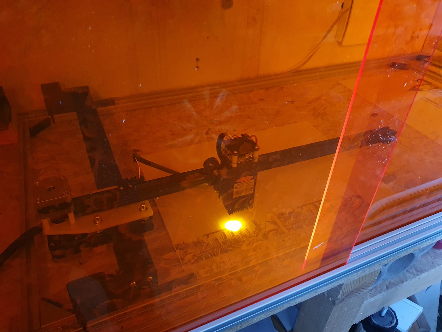
The laser has been turned on and is at the home position. What do you see which has changed?
There are 5 changes with one tough to see.
1 Like
I’ll grab the easy ones because I remember them from before:
- 3D printed spacers above the fan
- 3D printed exhaust cover over cut area
Is the hidden one something to do with focusing the laser?
Oh geesh, I forgot about that mod and didn’t consider it in the list. But that is one visible and the 3D printed exhaust cover is new. I consider the focus extension part if the fan shroud mod but it doesn’t have to be. ie it can be printed an added without the fan shroud.
Four more to go.
Argh!
People, help me!
I don’t have my Ortur to compare.
We need to identify FOUR other hacks from our Hack Master.
1 Like
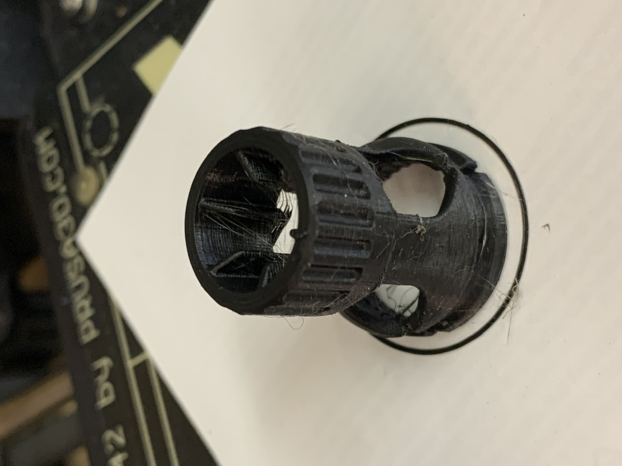
FWIW, the Air Assist mod is a bust since the design uses ~40mm of air chamber below the heatsink and the adjusment extension is 55mm long! Our focal length is ~55mm so that just isn’t going to work.
What I did get to work was the focus adjustment extension when I scaled it to 22.8mm X and Y and scaled it to 30mm in the Z. Now I can get my fat fingers under it to focus and there’s room to see the dot. Always on black paper now.
It might be a Fusion 360 project to make a similar air assist box but one with maybe 15mm below the heatsink and the fan inlet raised so there’s no loss in Y axis. The 3mm lost in X is insignificant. Heck, I gained one back by changing the GRBL software offset from 2mm to 1mm.
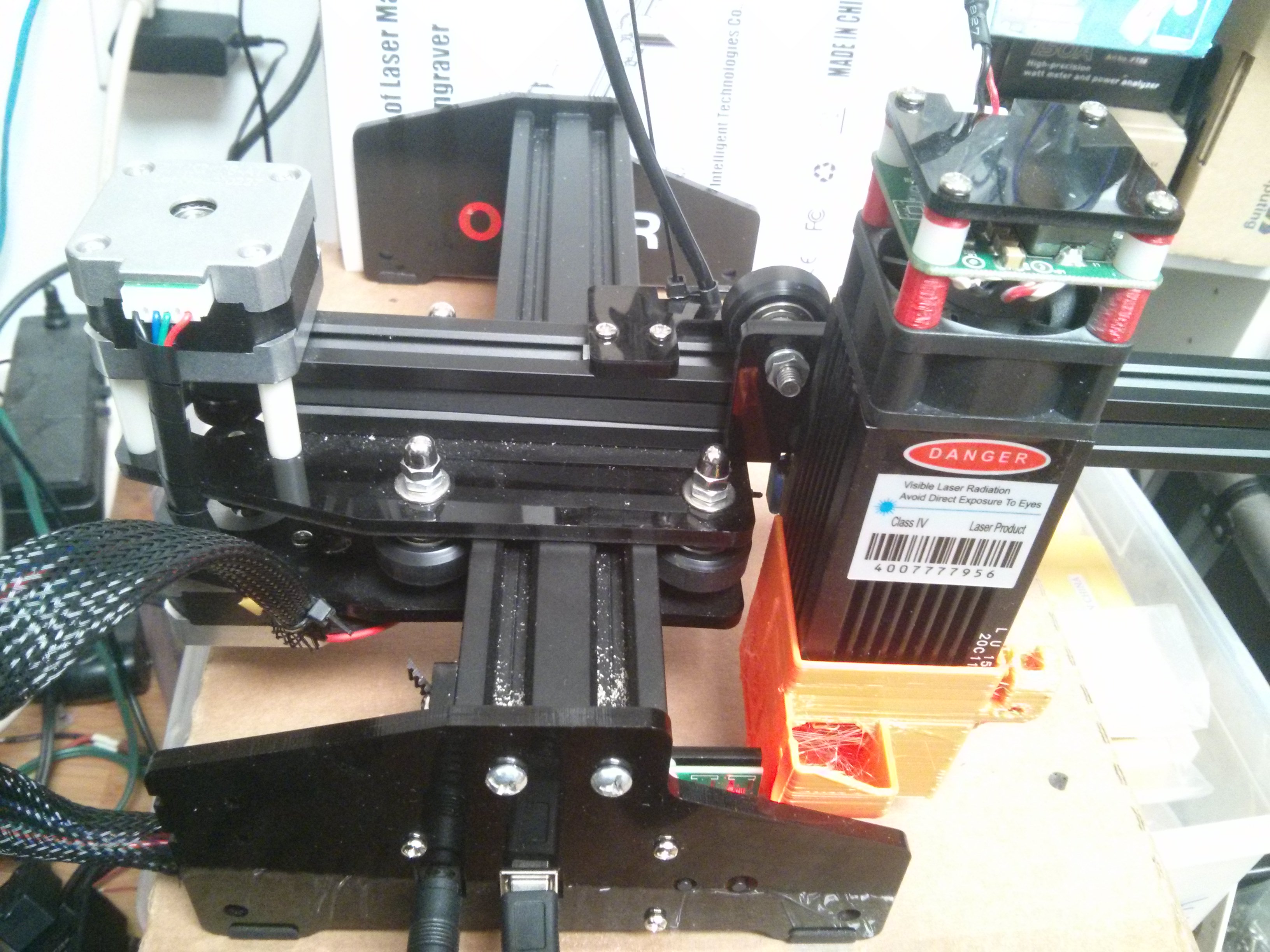
Besides the two Travis mentioned:
I moved the nuts UNDER the top acrylic X/Y axis mount to above the acrylic which lowered my X so I cn focus right on the material the laser is sitting on.
I got tired of reaching around the back to turn the thing on or get the cables plugged in so I removed the end caps/legs and swapped them. It’s homed so the bottom of the pic is the “front” of the machine. Notice the Ortur label on the opposite side facing inward.
This required swapping the controller board to the opposite side of the leg so it was inside and the cables plugged in from the outside.
I moved the Y axis end stop so it stopped at the edge of the backing of the controller board and I can move it more if needed for clearance for fans, etc.
I put a piece of 3mm plywood on the bumper for the X axis end stop so the plastic shroud didn’t hit the wheels before the end stop triggered.
I rotated the X axis stepper motor so the cables pointed towards the new direction of the controller board.
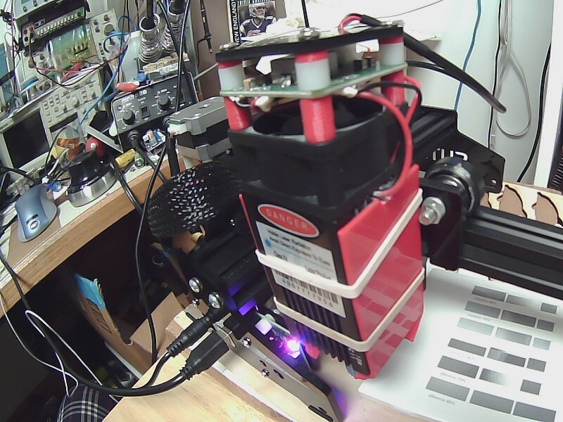
Not shown but recently I tried a 5V(USB powered) fan to blow smoke away and was surprised how well it worked. I will likely just make a mount on the laser head which allows me to clip the fan onto any of the 3 exposed sides of the laser head.
Attached are the 2 spacers(10mm and 2mm ) to do the fan hack which gives it more air.
Also attached is the side plates file to direct/deflect the air and also keep it moving along the heatsink for added cooling besides blowing some smoke away from the lens.
Another hack made evident by the issues @Rex ran into is to swap the Y axis belt/adjustment around so that the large plastic adjustment mount is on the other end of the machine.
Why? Because as it is now, you have to be very precise in how much belt you pull through the slot when you make the belt tensioning adjustment. If you pull too much then the large plastic adjustment mount is too far from the end of the extrusion and will likely get hit by the Y axis carriage BEFORE that carriage contacts the end stop switch. By swapping the belt and the adjustment/mounts around you don’t have to be so precise in belt length and just concentrate on belt tension.
Why not? When you move the large plastic adjustment mount to the other end, the Y axis carriage will contact that adjustment part before contacting the acrylic leg so your full Y axis size is about 10mm shorter than the full 160mm.
Better way? One better solution would have a slot in the acrylic leg and the belt tensioning adjustment done on the outside of the acrylic leg and therefore outside of the work area and away from any interference with the Y axis carriage.